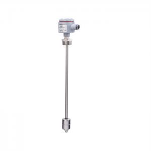
Description
Changes in the magnetization direction in ferromagnetic materials will cause changes in the lattice spacing of the medium, thereby changing the length and volume of the ferromagnetic materials, namely: magnetostriction, also known as the Wiedemann effect, and its reverse effect is called Villari effect. The magnetostrictive sensor is non-contact, reducing wear. It has the advantages of high resolution, high precision, high stability, high reliability, fast response time, and long working life. The sensor does not need to be recalibrated or regularly maintained.
working principle
The principle of the magnetostrictive sensor is to generate a strain pulse signal when two different magnetic fields intersect, and then calculate the time period required for this signal to be detected, thereby converting the accurate position. One of these two magnetic fields comes from the permanent magnet in the magnetic ring, and the other comes from the excitation pulse generated by the electronic components in the sensor electronics compartment. The excitation pulse travels at the speed of sound along a waveguide wire made of magnetostrictive material inside the sensor. When intersecting with the permanent magnetic field in the magnetic ring, the mechanical vibration generated by the waveguide wire forms a strain pulse due to the magnetostriction phenomenon. The strain pulse is quickly detected by sensing circuits in the electronics chamber. By multiplying the total time from the moment the excitation pulse is generated to the detection of the strain pulse by a fixed speed of sound, we can accurately calculate the position change of the magnet. This process is continuous, so whenever the position of the magnetic ring changes, the new position is quickly measured. Since the output signal is a true relative value, rather than a proportional or signal that needs to be re-amplified, there is no signal drift or value change, and there is no need for regular recalibration like other sensors.
Specification
★ Measuring range (mm) 80~5000mm
★ Power supply voltage: +11VDC~+24VDC
★ Output form/working voltage
Analog signal: 4~20mADC, 0~5VDC, 1~5VDC, 0~10VDC (+15VDC~+36VDC)
Digital signal: RS485
★ Load capacity: Voltage signal output with maximum load 2mA
Current signal output with maximum load 3KΩ
★ Nonlinear error ±0.05%FS; maximum error below 200mm is 100 μm
★ Repeatability error better than 0.002%FS
★ Resolution better than 0.002%FS
★ Hysteresis better than 0.002%FS
★ Working temperature 0~+70℃ -15~+60℃ -25~+70℃ -40~+85℃
★ Measuring rod material 0Cr18Ni9 (304) 316 stainless steel (special customization)
★ Electronic compartment shell material cast aluminum (1Cr18Ni9Ti optional)
★ Leading method PVC shielded cable (default length: 2.8m, can also be provided according to user requirements)
Aviation plug (not suitable for flameproof products) terminal block
★ Shell protection grade IP68
Things to note before installation
Read all installation instructions carefully to prevent the installation environment temperature, shock, vibration, pressure and size from exceeding the allowable range of the sensor; do not bend the measuring rod; do not subject the electronic component end or end of the sensor to a large impact; the electronic components of the sensor It is splash-proof but not submersible. Do not allow liquids to reach the top of the electronics compartment base. The user is responsible for the use environment, anti-corrosion, explosion-proof and function selection of the product. Sensors without special requirements cannot be used in flammable, explosive, corrosive, vapor and liquid situations that have chemical reactions or other damage to the sensor; after installation , the electronic warehouse should be protected.
Installation method
Built-in installation method:
1. Screw the sensor into the M18×1.5 mounting hole, and pay attention to processing the sealing surface of the "O" ring as shown in the figure.
2. According to the position of the magnetic ring, drill four threaded holes on the homemade piston, and fix the magnetic ring with M4×10 hexagon socket screws. The head of the screw faces the electronic compartment side of the sensor; the magnetic ring should be as concentric as possible with the measuring rod, but the eccentricity of the magnetic ring has no effect on the measurement accuracy. If there is any vibration, it is recommended to add a PTFE guide sleeve between the magnetic ring and the piston.
3. If the piston is made of magnetically conductive material, a non-magnetic conductive washer must be installed between the magnetic ring and the piston.
External installation method:
For sensors with a measurement range less than 1000mm, it is recommended to use the FW-1 installation accessory; for sensors with a measurement range greater than 1000mm, use a measuring rod bracket for installation.
1. Clamp the sensor with the sensor bracket and secure the bracket to the threads of the sensor with a lock nut.
2. Fix the magnetic ring on the magnetic ring bracket with M3×12 hexagon socket screws. When installing the magnetic ring on the measuring rod, the screw head should face the electronic compartment side; the magnetic ring should be as concentric as possible with the measuring rod and have no contact, but the magnetic ring should be Slight off-centreness of the ring will not affect sensor performance.
Wrap the fixing strip tightly around the end of the measuring rod and fix it with two M3×8 screws and two M3 nuts.
Note: The FW-1 installation accessory only provides one fixed slat, which should be fixed within 50mm from the end of the measuring rod; the measuring rod bracket installation accessory has three fixed slats. The installation method is: one fixed slat is fixed about 25mm from the end. Inside, the other two are evenly distributed on the measuring rod. Then fix the entire initially installed sensor with homemade screws according to the installation requirements.
Adjustment
The sensor has been calibrated to zero and full scale at the factory. Due to the long-term stability of the sensor, no adjustments are required throughout the entire life cycle. Therefore, in order to improve reliability, the sensor does not have a port for adjustment. Please use a parameter-calibrated secondary instrument for measurement. If the user needs to reset the zero point and full scale, please contact our company.
Packing & Delivery

FAQ
1. Q: What information need to be provided to choose the suitable model?
A: Application field, Nominal pressure ,Medium & medium temperture , Power supply , Output,
Flow range, Accuracy, Connection and other parameters.
2. Q: Are you a trade company or a manufacturer?
A: We are an ISO approved manufacturer specialized in level and flow measuring instruments.
OEM & ODM service are available. Welcome to visit us in China.
3. Q: What is your MOQ?
A: To start our cooperation, sample order is acceptable.
4. Q: What is your delivery date for the Intelligent Mini Micro Turbine Fuel Oil Diesel Flow Meter?
A: The delivery date is about 3-15 working days after receipt of payment.
5. Q: What is your payment terms?
A: We support T/T, PayPal ,Western Union.
For mass production order, it is 30% deposit in advance and 70% balance before shipment.
6. Q: Do you have a warranty for the Flow Meter?
A: Yes, we have the warranty of 12 months.